ShaderGraphでVoronoiエッジ距離
環境
Unity2022.2.2f1
ShaderGraph14.0.4
概要
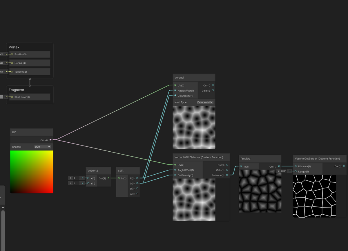
CustomFunctionノードを使用して、標準のvoronoiノードにプラスしてエッジまでの距離を返すようにしたノード用の関数を作成してみました。
※for文を[unroll]しないと自分の環境だとバグるので入れています。
コード
#include "Packages/com.unity.render-pipelines.core/ShaderLibrary/Hashes.hlsl"

float2 Unity_Voronoi_RandomVector_Deterministic_float (float2 UV, float offset)
{
    Hash_Tchou_2_2_float(UV, UV);
    return float2(sin(UV.y * offset), cos(UV.x * offset)) * 0.5 + 0.5;
}

void VoronoiWithDistance_float(float2 UV, float AngleOffset, float CellDensity, out float Out, out float Cells, out float Distance)
{
    // first pass: regular voronoi
    float2 g = floor(UV * CellDensity);
    float2 f = frac(UV * CellDensity);
    float t = 8.0;
    float3 res = float3(8.0, 0.0, 0.0);

    float2 mr;

    [unroll]
    for (int y = -1; y <= 1; y++)
    {
        [unroll]
        for (int x = -1; x <= 1; x++)
        {
            float2 lattice = float2(x, y);
            float2 offset = Unity_Voronoi_RandomVector_Deterministic_float(lattice + g, AngleOffset);
            float d = distance(lattice + offset, f);
            if (d < res.x)
            {
                res = float3(d, offset.x, offset.y);
                Out = res.x;
                Cells = res.y;

                mr = lattice + offset - f;
            }
        }
    }
    // second pass: distance to borders
    float md = 8.0;
    [unroll]
    for (int y = -2; y <= 2; y++)
    {
        [unroll]
        for (int x = -2; x <= 2; x++)
        {
            float2 lattice = float2(x, y);
            float2 offset = Unity_Voronoi_RandomVector_Deterministic_float(lattice + g, AngleOffset);
            float2 r = lattice + offset - f;

            if (dot(mr - r, mr - r) > 0.0001)
            {
                md = min(md, dot(0.5 * (mr + r), normalize(r - mr)));
            }
        }
    }
    Distance = md;//float3(md, mr.x, mr.y);
}

void VoronoiGetBorder_float(float Distance, float Length, out float Out)
{
    Out = 1.0 - smoothstep(0.0, Length, Distance);
}
参考
Inigo Quilez :: computer graphics, mathematics, shaders, fractals, demoscene and more
【Unity】リピート感なしのテクスチャマッピングの再現【Blender】 - 夜はCGの時間
Unity Shader Graph custom node for precise voronoi borders · GitHub
[Unity] Shader Graph でノイズ関数を改造してタイリングに対応するカスタムノードを作る(改) - Qiita
わけわからない
標準のVoronoiノードが正しく動作しない。赤くなる。何でこんな結果になるのか。

コードでも赤になる。
ただしVoronoi関数のforの上に[unroll]を付けると直る。
正しいのかはわからない。
Shader "Unlit/TestVoronoi"
{
    Properties
    {
    }

    CGINCLUDE
    //#pragma enable_d3d11_debug_symbols
    #include "UnityCG.cginc"
    // Graph Includes
    #include "Packages/com.unity.render-pipelines.core/ShaderLibrary/Hashes.hlsl"

    // Graph Functions
    float2 Unity_Voronoi_RandomVector_Deterministic_float (float2 UV, float offset)
    {
        Hash_Tchou_2_2_float(UV, UV);
        return float2(sin(UV.y * offset), cos(UV.x * offset)) * 0.5 + 0.5;
    }

    void Unity_Voronoi_Deterministic_float(float2 UV, float AngleOffset, float CellDensity, out float Out, out float Cells)
    {
        float2 g = floor(UV * CellDensity);
        float2 f = frac(UV * CellDensity);
        float t = 8.0;
        float3 res = float3(8.0, 0.0, 0.0);
        [unroll]
        for (int y = -1; y <= 1; y++)
        {
            [unroll]
            for (int x = -1; x <= 1; x++)
            {
                float2 lattice = float2(x, y);
                float2 offset = Unity_Voronoi_RandomVector_Deterministic_float(lattice + g, AngleOffset);
                float d = distance(lattice + offset, f);
                if (d < res.x)
                {
                    res = float3(d, offset.x, offset.y);
                    Out = res.x;
                    Cells = res.y;
                }
            }
        }
    }

    void Unity_ColorspaceConversion_HSV_RGB_float(float3 In, out float3 Out)
    {
        float4 K = float4(1.0, 2.0 / 3.0, 1.0 / 3.0, 3.0);
        float3 P = abs(frac(In.xxx + K.xyz) * 6.0 - K.www);
        Out = In.z * lerp(K.xxx, saturate(P - K.xxx), In.y);
    }

    ENDCG

    SubShader
    {
        Tags { "RenderType"="Opaque" }
        LOD 100

        Pass
        {
            CGPROGRAM
            #pragma vertex vert
            #pragma fragment frag

            struct appdata
            {
                float4 vertex : POSITION;
                float2 uv : TEXCOORD0;
            };

            struct v2f
            {
                float4 vertex : SV_POSITION;
                float2 uv : TEXCOORD0;
            };

            v2f vert (appdata v)
            {
                v2f o;
                o.vertex = UnityObjectToClipPos(v.vertex);
                o.uv = v.uv;
                return o;
            }

            fixed4 frag (v2f i) : SV_Target
            {
                float voroValue;
                float voroCells;
                Unity_Voronoi_Deterministic_float(i.uv, 6, 5, voroValue, voroCells);
                fixed3 rgb;
                Unity_ColorspaceConversion_HSV_RGB_float(float3(voroCells, 1, 1), rgb);
                return fixed4(rgb, 1);
            }
            ENDCG
        }
    }
}
描画順に依存しない半透明処理(OIT)
環境
Unity2022.2.2f1
概要

画像は複数のオブジェクトがあるように見えますが1つです。
Unityで生成した複数のオブジェクトのMeshをCombineMeshして1つのMeshにしています。
Unityだと通常、半透明はオブジェクト単位でソートされ、画面奥からZ書き込みなしで描画します。
半透明のMesh自体が複雑だと、オブジェクト単位のソートでは見え方が破綻してしまいます。
このOITの手法はピクセル単位でわりと正しく見えるように近似するものです。
詳しくは参考のページに丁寧に書いてあります。
コード
using UnityEngine;
using UnityEngine.Rendering;
using UnityEngine.UI;

public class TestOit : MonoBehaviour
{
    [SerializeField] Shader _shClear = null;
    [SerializeField] Shader _shCombine = null;
    private RenderTexture[] _renderTexs = new RenderTexture[2];
    private Material _matClear = null;
    private Material _matCombine = null;
    private static int _spTargetTex0 = Shader.PropertyToID("_TargetTex0");
    private static int _spTargetTex1 = Shader.PropertyToID("_TargetTex1");

    private void OnEnable()
    {
        _matClear = new Material(_shClear);
        _matCombine = new Material(_shCombine);

        var camera = Camera.main;
        _renderTexs[0] = new RenderTexture(camera.pixelWidth, camera.pixelHeight, 24, UnityEngine.Experimental.Rendering.DefaultFormat.HDR);
        _renderTexs[1] = new RenderTexture(camera.pixelWidth, camera.pixelHeight, 0, UnityEngine.Experimental.Rendering.DefaultFormat.HDR);

        var rts = new RenderBuffer[]
        {
            _renderTexs[0].colorBuffer,
            _renderTexs[1].colorBuffer,
        };
        camera.SetTargetBuffers(rts, _renderTexs[0].depthBuffer);
        Shader.SetGlobalTexture(_spTargetTex0, _renderTexs[0]);
        Shader.SetGlobalTexture(_spTargetTex1, _renderTexs[1]);

        var cbClear = new CommandBuffer();
        cbClear.name = "OitClear";
        cbClear.DrawProcedural(Matrix4x4.identity, _matClear, 0, MeshTopology.Quads, 4, 1);
        camera.AddCommandBuffer(CameraEvent.AfterSkybox, cbClear);

        var cbCombine = new CommandBuffer();
        cbCombine.name = "OitCombine";
        cbCombine.SetRenderTarget(-1);
        cbCombine.Blit(null, BuiltinRenderTextureType.CurrentActive, _matCombine);
        camera.AddCommandBuffer(CameraEvent.AfterEverything, cbCombine);
    }

    private void OnDisable()
    {
        Camera.main.targetTexture = null;
        for(int i = 0; i < _renderTexs.Length; i++)
            _renderTexs[i].Release();

        if(_matClear != null)
            GameObject.Destroy(_matClear);
        if(_matCombine != null)
            GameObject.Destroy(_matCombine);
    }
}
Shader "Hidden/OIT/Clear"
{
    Properties
    {
    }
    SubShader
    {
        ZTest Always
        Cull Back
        ZWrite Off
        Fog { Mode Off }
        // Color0
        ColorMask A 0
        // Color1

        Pass
        {
            CGPROGRAM

            #pragma vertex vert
            #pragma fragment frag

            struct a2v
            {
                uint vertexId : SV_VertexID;
            };

            struct v2f
            {
                float4 pos : SV_POSITION;
            };

            struct outf
            {
                fixed4 color0 : SV_Target0;
                fixed4 color1 : SV_Target1;
            };

            v2f vert(a2v v)
            {
                float3 posCSs[4] =
                {
                    float3(-1,  1, 0),
                    float3(-1, -1, 0),
                    float3( 1, -1, 0),
                    float3( 1,  1, 0),
                };
                v2f o;
                o.pos = float4(posCSs[v.vertexId], 1);
                return o;
            }

            outf frag(v2f i)
            {
                outf o;
                o.color0 = fixed4(0,0,0,1);
                o.color1 = fixed4(0,0,0,0);
                return o;
            }
            ENDCG
        }
    }
}
Shader "Hidden/OIT/Combine"
{
    Properties
    {
    }
    SubShader
    {
        ZTest Always
        Cull Off
        ZWrite Off
        Fog { Mode Off }

        Pass
        {
            CGPROGRAM

            #pragma vertex vert
            #pragma fragment frag

            struct a2v
            {
                float4 vertex : POSITION;
                float2 texcoord : TEXCOORD0;
            };

            struct v2f
            {
                float4 pos : SV_POSITION;
                float2 texcoord : TEXCOORD0;
            };

            sampler2D _TargetTex0;
            sampler2D _TargetTex1;
            v2f vert(a2v v)
            {
                v2f o;
                o.pos = UnityObjectToClipPos(v.vertex);
                o.texcoord = v.texcoord;
                return o;
            }

            fixed4 frag(v2f i) : SV_Target
            {
                fixed4 background = tex2D(_TargetTex0, i.texcoord);
                float revealage = background.a;
                float4 accum = tex2D(_TargetTex1, i.texcoord);
                fixed3 rgb = fixed3(accum.rgb / clamp(accum.a, 1e-4, 5e4));
                rgb = rgb * (1.0 - revealage) + background.rgb * revealage;
                return fixed4(rgb, 1.0);

            }
            ENDCG
        }
    }
}
「Unlit/OIT/Transparent」このシェーダを半透明オブジェクトに適用する
Shader "Unlit/OIT/Transparent"
{
    Properties
    {
        _Color("Color", Color) = (1, 1, 1, 1)
    }
    SubShader
    {
        Tags { "RenderType" = "Transparent" "Queue" = "Transparent" }
        LOD 100
        ZWrite Off
        // Color0
        ColorMask A 0
        Blend 0 Zero OneMinusSrcAlpha
        // Color1
        Blend 1 One One

        Pass
        {
            CGPROGRAM
            #pragma vertex vert
            #pragma fragment frag

            #include "UnityCG.cginc"

            struct appdata
            {
                float4 vertex : POSITION;
            };
            float4 _Color;

            struct v2f
            {
                float4 vertex : SV_POSITION;
                float posVS_z : TEXCOORD0;
            };

            struct outf
            {
                fixed4 color0 : SV_Target0;
                fixed4 color1 : SV_Target1;
            };

            v2f vert (appdata v)
            {
                v2f o;
                o.vertex = UnityObjectToClipPos(v.vertex);
                o.posVS_z = abs(mul(UNITY_MATRIX_MV, v.vertex).z);
                return o;
            }

            outf frag (v2f i)
            {
                outf o;
                float4 col = _Color;
                //return col;

                o.color0 = fixed4(0,0,0,col.a);
                float z = i.posVS_z;
                float w = col.a * max(1e-2, min(3 * 1e3, 10.0/(1e-5 + pow(z/5, 2) + pow(z/200, 6))));
                o.color1 = fixed4(col.rgb * col.a, col.a) * w;
                return o;
            }
            ENDCG
        }
    }
}
参考
UnityでOIT(Order Independent Tranceparency) - UnityShader 入門
GitHub - candycat1992/OIT_Lab: :pencil2: Order-independent Transparent in Unity
フェイクスポットライト
環境
Unity2022.2.2f1
概要
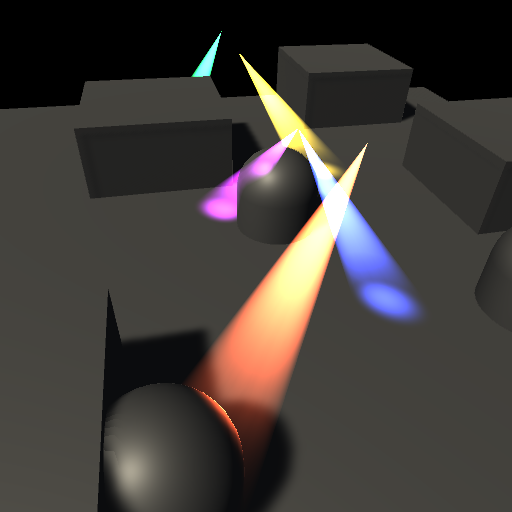
フェイクスポットライトの実装テストです。
法線を考慮していません。
デカール処理がOFFの場合ならもっとシンプルになりますが、面倒なので分けていません。
円錐の頂点部分が原点、底がZ方向で円の中心部分が0.0,0.0,1.0、半径が0.5のメッシュを使用しています。
コード
Shader "Custom/SSSpotDecalLight"
{
    Properties{
        [HDR]_Color("Color", Color) = (1, 1, 1, 1)
        [KeywordEnum(Off, On)] _VolumeEnabled("Volume Enabled", Float) = 1
        [KeywordEnum(Off, On)] _DecalEnabled("Decal Enabled", Float) = 1
        _MainTex ("MainTex", 2D) = "white" {}
        _Rim ("Rim", Range(0.0, 1.0)) = 1.0
    }

    CGINCLUDE
    #pragma enable_d3d11_debug_symbols
    #pragma shader_feature _ _VOLUMEENABLED_ON
    #pragma shader_feature _ _DECALENABLED_ON
    #include "UnityCG.cginc"

    float4 _Color;
    // Volume
    sampler2D _MainTex;
    float4 _MainTex_ST;
    fixed _Rim;
    // Decal
    sampler2D _CameraDepthNormalsTexture;
    sampler2D _CameraDepthTexture;

    struct appdata
    {
        float4 vertex : POSITION;
        float3 normal : NORMAL;
        float3 texcoord : TEXCOORD0;
    };

    struct v2f
    {
        float4 positionCS :SV_POSITION;
        // Volume
        float4 color : COLOR;
        float2 texcoord : TEXCOORD0;
        // Decal
        float4 positionSS : TEXCOORD1;
        float3 positionWS : TEXCOORD2;
        float dotRadius : TEXCOORD3;
        float3 lightDirVS : TEXCOORD4;
    };
    ENDCG

    SubShader
    {
        Tags { "RenderType" = "Transparent" "Queue" = "Transparent" }
        Pass
        {
            ZWrite Off
            Cull Off
            Lighting Off
            Blend SrcAlpha One

            CGPROGRAM
            #pragma vertex vert
            #pragma fragment frag

            v2f vert(appdata v)
            {
                v2f o;
                o.positionCS = UnityObjectToClipPos(v.vertex);

                // Decal
                o.positionSS = ComputeScreenPos(o.positionCS);
                o.positionWS = mul(unity_ObjectToWorld, v.vertex).xyz;

                float3 vec = UNITY_MATRIX_M._m02_m12_m22 + UNITY_MATRIX_M._m00_m10_m20 * 0.5;
                o.dotRadius = dot(normalize(vec), normalize(UNITY_MATRIX_M._m02_m12_m22));
                o.lightDirVS = mul(UNITY_MATRIX_V, UNITY_MATRIX_M._m02_m12_m22);

                // Volume
                float3 viewDirOS = normalize(ObjSpaceViewDir(v.vertex));
                float NdotE = abs(dot(v.normal, viewDirOS));
                o.color.rgb = smoothstep(1 - _Rim, 1.0, NdotE) *_Color.rgb;
                o.color.a = 1.0 - (saturate(v.vertex.z - 0.5) / 0.5);

                o.texcoord = TRANSFORM_TEX(v.texcoord,_MainTex);

                return o;
            }

            half4 frag(v2f i) : Color
            {
                half4 col = fixed4(0,0,0,_Color.a);
                // Decal
                const float far = _ProjectionParams.z;
                float2 positionSS = i.positionSS.xy / i.positionSS.w;
                float depth;
                float3 normalVS;
                float4 depthAndNormal = tex2D(_CameraDepthNormalsTexture, positionSS);
                DecodeDepthNormal(depthAndNormal, depth, normalVS);
                float eyeDepth = depth * far;
                eyeDepth = LinearEyeDepth(SAMPLE_DEPTH_TEXTURE(_CameraDepthTexture, positionSS.xy));
                float3 cameraForwardDir = -UNITY_MATRIX_V._m20_m21_m22;
                float3 viewDirWS = normalize(UnityWorldSpaceViewDir(i.positionWS));
                float3 positionWS = ((eyeDepth * viewDirWS * (1.0 / dot(cameraForwardDir, viewDirWS))) + _WorldSpaceCameraPos);

                float3 vecWS;
                float power;
                float lightRadius = length(UNITY_MATRIX_M._m00_m10_m20) * 0.5;
                half3 rgb = tex2D(_MainTex, i.texcoord);
#if defined(_VOLUMEENABLED_ON)
                // Volume
                vecWS = positionWS - i.positionWS;
                power = saturate(length(vecWS) / lightRadius);
                half3 volumeRgb = rgb * i.color.rgb * i.color.a * power;
                col.rgb += volumeRgb.rgb;
#endif

#if defined(_DECALENABLED_ON)
                float lenLightDirWS = length(UNITY_MATRIX_M._m02_m12_m22);
                vecWS = positionWS - UNITY_MATRIX_M._m03_m13_m23;
                float lenVecWS = length(vecWS);
                power = lenVecWS > lenLightDirWS ? 0 : saturate(1.0 - (lenVecWS - (lenLightDirWS - lightRadius)) / lightRadius);
                float d = dot(normalize(vecWS), normalize(UNITY_MATRIX_M._m02_m12_m22));
                power *= saturate(d - i.dotRadius) / (1.0 - i.dotRadius);

                float NdotL = saturate(dot(normalVS, normalize(-i.lightDirVS)));
                power *= NdotL;

                half3 decalRgb = smoothstep(1 - _Rim, 1.0, power) * power *_Color.rgb;
                col.rgb += decalRgb.rgb;
#endif
                return col;
            }
            ENDCG
        }
    }
}
参考
SmokeLighting(SixWayLightmap)
環境
Unity2022.2.2f1
概要

UnityがHDRPでVfxGraphに実装した「Six Way Smoke Lit」的なもののテストです
ポイントライトはRenderModeを「Important」に設定しています
QuadのGameObjectを作成して、マテリアルを設定すれば確認できます
テクスチャは参考のUnityのブログ記事から使えるもののリンクがあります
コード
Shader "lit/SmokeSixWayLightmap"
{
    Properties
    {
        _PisitiveTex("PisitiveTex", 2D) = "white" {}
        _NegativeTex("NegativeTex", 2D) = "white" {}
        _TexDivideX("TexDivideX", int) = 1
        _TexDivideY("TexDivideY", int) = 1
        [HDR]_EmissiveColor("EmissiveColor", Color) = (0,1,0,1)
    }

    CGINCLUDE
    #pragma enable_d3d11_debug_symbols
    #include "UnityCG.cginc"
    #include "Lighting.cginc"

#define BILLBOARD

    struct appdata
    {
        float4 vertex : POSITION;
        float2 texcoord : TEXCOORD;
#if !defined(BILLBOARD)
        float3 normal : NORMAL;
        float4 tangent : TANGENT;
#endif
    };

    struct v2f
    {
        float4 pos : SV_POSITION;
        float2 texcoord : TEXCOORD0;
        float3 lightDirTS : TEXCOORD1;
        float3 lightDirTS2 : TEXCOORD2;
        float3 lightColor : TEXCOORD3;
        float3 lightColor2 : TEXCOORD4;
    };

    fixed4 _EmissiveColor;
    sampler2D _PisitiveTex;
    sampler2D _NegativeTex;
    uint _TexDivideX;
    uint _TexDivideY;

    float ComputeLightMap(float3 lightDirTS, float4 colPositiveRTBA, float4 colNegativeLBFE)
    {
        float lr = (lightDirTS.x > 0.0) ? (colPositiveRTBA.x) : (colNegativeLBFE.x);
        float tb = (lightDirTS.y > 0.0) ? (colPositiveRTBA.y) : (colNegativeLBFE.y);
        float fb = (-lightDirTS.z > 0.0) ? (colPositiveRTBA.z) : (colNegativeLBFE.z);
        float lightMap = lr * lightDirTS.x * lightDirTS.x
                       + tb * lightDirTS.y * lightDirTS.y
                       + fb * lightDirTS.z * lightDirTS.z;
        return lightMap;
    }

    // Shade4PointLightsから法線の処理を消したもの
    float3 FourPointLightsColor(
        float4 lightPosX,
        float4 lightPosY,
        float4 lightPosZ,
        float3 lightColor0,
        float3 lightColor1,
        float3 lightColor2,
        float3 lightColor3,
        float4 lightAttenSq,
        float3 pos)
    {
        // to light vectors
        float4 toLightX = lightPosX - pos.x;
        float4 toLightY = lightPosY - pos.y;
        float4 toLightZ = lightPosZ - pos.z;

        // squared lengths
        float4 lengthSq = 0;
        lengthSq += toLightX * toLightX;
        lengthSq += toLightY * toLightY;
        lengthSq += toLightZ * toLightZ;

        // don't produce NaNs if some vertex position overlaps with the light
        lengthSq = max(lengthSq, 0.000001);

        // attenuation
        float4 atten = 1.0 / (1.0 + lengthSq * lightAttenSq);
        float4 diff = atten;

        // final color
        float3 col = 0;
        col += lightColor0 * diff.x;
        col += lightColor1 * diff.y;
        col += lightColor2 * diff.z;
        col += lightColor3 * diff.w;

        return col;
    }

    ENDCG

    SubShader
    {
        Tags
        {
            "Queue"="Transparent"
            "RenderType"="Transparent"
            "IgnoreProjector"="True"
            "LightMode" = "ForwardBase"
        }
        Pass
        {
            ZWrite Off
            Cull Back
            Blend SrcAlpha OneMinusSrcAlpha

            CGPROGRAM
            #pragma multi_compile_fwdbase nolightmap nodirlightmap nodynlightmap
            #pragma vertex vert
            #pragma fragment frag

            v2f vert(appdata v)
            {
                v2f o;
#if defined(BILLBOARD)
                // Billboard
                float3x3 mtxRot = unity_ObjectToWorld;
                mtxRot._m00_m10_m20 = normalize(mtxRot._m00_m10_m20);
                mtxRot._m01_m11_m21 = normalize(mtxRot._m01_m11_m21);
                mtxRot._m02_m12_m22 = normalize(mtxRot._m02_m12_m22);
                v.vertex.xyz = mul(v.vertex.xyz, mul(UNITY_MATRIX_V, mtxRot));
#endif
                // TextureAnimation
                const uint dx = _TexDivideX;
                const uint dy = _TexDivideY;
                const float tdx = 1.0 / dx;
                const float tdy = 1.0 / dy;
                uint index = (uint)fmod(_Time.y * 30.0, dx * dy);
                uint ix = index % dx;
                uint iy = (dy - 1) - (index / dx);
                o.texcoord = float2(v.texcoord.x, v.texcoord.y) * float2(tdx, tdy);
                o.texcoord.x += ix * tdx;
                o.texcoord.y += iy * tdy;

                o.pos = UnityObjectToClipPos(v.vertex);
                float3 posWS = mul(unity_ObjectToWorld, v.vertex).xyz;
#if defined(BILLBOARD)
                float3 normalWS = -unity_CameraToWorld._m02_m12_m22;
                float3 tangentWS = unity_CameraToWorld._m00_m10_m20;
                float3 bitangentWS = unity_CameraToWorld._m01_m11_m21;
#else
                fixed3 normalWS = UnityObjectToWorldNormal(v.normal);
                fixed3 tangentWS = UnityObjectToWorldDir(v.tangent.xyz);
                fixed3 bitangentWS = cross(normalWS, tangentWS) * v.tangent.w;
#endif
                float3x3 mtxWSToTS = float3x3(tangentWS, bitangentWS, normalWS);

                // DirectionalLight
                float3 lightDirWS = _WorldSpaceLightPos0.xyz;
                o.lightDirTS = mul(mtxWSToTS, lightDirWS);
                o.lightColor = _LightColor0.rgb;

                // PointLights
                float3 lightPos = float3(0,0,0);
                uint lightCount = 0;
                [unroll]
                for (uint i = 0; i < 4; i++)
                {
                    lightPos += float3(unity_4LightPosX0[i], unity_4LightPosY0[i], unity_4LightPosZ0[i]);
                    lightCount += (unity_LightColor[i].a > 0) ? 1 : 0;
                }
                lightPos /= lightCount;

                float3 lightDirWS2 = normalize(lightPos - posWS.xyz);
                o.lightDirTS2 = mul(mtxWSToTS, lightDirWS2);
                o.lightColor2 = FourPointLightsColor(
                  unity_4LightPosX0,
                  unity_4LightPosY0,
                  unity_4LightPosZ0,
                  unity_LightColor[0].rgb,
                  unity_LightColor[1].rgb,
                  unity_LightColor[2].rgb,
                  unity_LightColor[3].rgb,
                  unity_4LightAtten0,
                  posWS);
                return o;
            }

            half4 frag(v2f In) : COLOR
            {
                half4 colPositive = tex2D(_PisitiveTex, In.texcoord);
                half4 colNegative = tex2D(_NegativeTex, In.texcoord);

                // DirectionalLight
                float3 lightDirTS = normalize(In.lightDirTS);
                float lightmap01 = ComputeLightMap(lightDirTS, colPositive, colNegative);
                // PointLights
                float3 lightDirTS2 = normalize(In.lightDirTS2);
                float lightmap02 = ComputeLightMap(lightDirTS2, colPositive, colNegative);

                half3 rgb01 = lightmap01 * In.lightColor;
                half3 rgb02 = lightmap02 * In.lightColor2;
                half3 rgb = rgb01 + rgb02;

                half4 col = half4(rgb, colPositive.a);
                col.rgb += _EmissiveColor.rgb * colNegative.a;
                return col;
            }
            ENDCG
        }
    }
}
参考
Visual Effect Graph の 6 ウェイライティングを使ったリアルな煙のライティング | Unity Blog
GitHub - keijiro/SixWaySmokeTest
6-way lightmap WIP - #20 by Aaron - Real Time VFX
この記事はFrontとBackに近似値を使用してチャンネルを節約したものを解説している?
Smoke Lighting and texture re-usability in Skull & Bones - Real Time VFX
ディレクショナルライトの方向
環境
Unity2022.2.2f1
概要

_WorldSpaceLightPos0で得るディレクショナルライトの方向は逆を向いている
Houdini ApprenticeでVAT出力
環境
Houdini Apprentice 19.5.534
python3.9 Fbx Sdk
概要
Houdiniでパーティクルを独自VATとしてExr形式のファイルに出力します
Unity上で再生できるプログラムを作ったところ、同じように動作しました
パーティクルは参考の動画をみて作成しました。バージョンが上がり多少違いましたが、同じような感じに出来ました
また動画はライフに基づいてカラーを0に近づけていますが、こちらはAlphaのアトリビュートを追加してそれに対して行っています
Alphaというアトリビュートを追加すると勝手にアルファブレンドになる模様

import OpenEXR
import numpy as np
import Imath
import json

fps = int(hou.fps())
node = hou.pwd()
targetNode = hou.node(node.parm("node").eval())
startFrame = node.parm("startFrame").eval()
endFrame = node.parm("endFrame").eval()
imageWidth = node.parm("imageWidth").eval()
imageHeight = node.parm("imageHeight").eval()
outputDir = node.parm("outputDir").eval()

imageSize = imageWidth * imageHeight
channelNum = 4
strideTexelNum = 2
pixelType = Imath.PixelType.HALF
dataType = np.float16
texels = np.zeros((imageSize, channelNum), dtype=dataType)
texIndex = 0
texelIndex = 0

def writeImage():
    header = OpenEXR.Header(imageWidth, imageHeight)
    header['channels'] = {
        'R': Imath.Channel(Imath.PixelType(pixelType)),
        'G': Imath.Channel(Imath.PixelType(pixelType)),
        'B': Imath.Channel(Imath.PixelType(pixelType)),
        'A': Imath.Channel(Imath.PixelType(pixelType))
    }
    header['compression'] =Imath.Compression(Imath.Compression.NO_COMPRESSION)
    outputPath = f'{outputDir}/output{texIndex}.exr';
    print(outputPath)
    output = OpenEXR.OutputFile(outputPath, header)
    output.writePixels({
        'R': texels[:,0].astype(dataType).tostring(),
        'G': texels[:,1].astype(dataType).tostring(),
        'B': texels[:,2].astype(dataType).tostring(),
        'A': texels[:,3].astype(dataType).tostring()
    })
    output.close()

def writePoints(frame, maxPointNum):
    global texels, texIndex, texelIndex

    geo = targetNode.geometry()
    pointNum = len(geo.points())
    texelNum = maxPointNum * strideTexelNum
    if (texelIndex + texelNum) > imageSize:
        writeImage()
        texIndex += 1
        texelIndex = 0
        texels[:,] = [0.0, 0.0, 0.0, 0.0]

    for point in geo.points():
        pos = point.position()
        texels[texelIndex + 0,] = [pos.x(), pos.y(), pos.z(), 0.0]
        color = point.attribValue('Cd')
        alpha = point.attribValue('Alpha')
        texels[texelIndex + 1,] = [color[0], color[1], color[2], alpha]
        texelIndex += strideTexelNum

    dummyNum = maxPointNum - pointNum
    for i in range(dummyNum):
        texels[texelIndex + 0,] = [0.0, 0.0, 0.0, 0.0]
        texels[texelIndex + 1,] = [0.0, 0.0, 0.0, 0.0]
        texelIndex += strideTexelNum

def main():
    global texIndex, texelIndex

    maxPointNum = 0
    frameNum = (endFrame - startFrame) + 1
    for i in range(frameNum):
        frame = startFrame + i
        hou.setFrame(frame)
        geo = targetNode.geometry()
        maxPointNum = max(maxPointNum, len(geo.points()))

    texIndex = 0
    texelIndex = 0
    for i in range(frameNum):
        frame = startFrame + i
        hou.setFrame(frame)
        writePoints(frame, maxPointNum)
    if texelIndex > 0 :
        writeImage()
        texIndex += 1

    paramDict = {}
    paramDict['texNum'] = texIndex;
    paramDict['fps'] = fps
    paramDict['frameNum'] = frameNum;
    paramDict['maxPointNumInFrame'] = maxPointNum;
    jsonData = json.dumps(paramDict, ensure_ascii=False)
    print(jsonData)
    outputPath = f'{outputDir}/output.json';
    f = open(outputPath, 'w')
    f.write(jsonData)
    f.close()

main()
参考
Houdini ダイナミクス基本講座 Part1:ダイナミクスシミュレーションの流れ - YouTube
プリミティブ版
HdrpVatExample/Fluid.hip at master · keijiro/HdrpVatExample · GitHub
に三角形分割、Color、Normal、UVを追加したものを使用してテスト
import OpenEXR
import numpy as np
import Imath
import json

fps = int(hou.fps())
node = hou.pwd()
targetNode = hou.node(node.parm("node").eval())
startFrame = node.parm("startFrame").eval()
endFrame = node.parm("endFrame").eval()
imageWidth = node.parm("imageWidth").eval()
imageHeight = node.parm("imageHeight").eval()
outputDir = node.parm("outputDir").eval()

imageSize = imageWidth * imageHeight
channelNum = 4
strideTexelNum = 3
pixelType = Imath.PixelType.HALF
dataType = np.float16
texels = np.zeros((imageSize, channelNum), dtype=dataType)
texIndex = 0
texelIndex = 0
pointInface = 3

def writeImage():
    header = OpenEXR.Header(imageWidth, imageHeight)
    header['channels'] = {
        'R': Imath.Channel(Imath.PixelType(pixelType)),
        'G': Imath.Channel(Imath.PixelType(pixelType)),
        'B': Imath.Channel(Imath.PixelType(pixelType)),
        'A': Imath.Channel(Imath.PixelType(pixelType))
    }
    header['compression'] =Imath.Compression(Imath.Compression.NO_COMPRESSION)
    outputPath = f'{outputDir}/output{texIndex}.exr';
    print(outputPath)
    output = OpenEXR.OutputFile(outputPath, header)
    output.writePixels({
        'R': texels[:,0].astype(dataType).tostring(),
        'G': texels[:,1].astype(dataType).tostring(),
        'B': texels[:,2].astype(dataType).tostring(),
        'A': texels[:,3].astype(dataType).tostring()
    })
    output.close()

def writeFaces(frame, maxPointNum):
    global texels, texIndex, texelIndex

    geo = targetNode.geometry()
    texelNum = maxPointNum * strideTexelNum
    pointNum = len(geo.prims()) * pointInface
    if pointNum > maxPointNum:
        print(f'error pointNum:{pointNum} maxPointNum:{maxPointNum}')
        return

    if (texelIndex + texelNum) > imageSize:
        writeImage()
        texIndex += 1
        texelIndex = 0
        texels[:,] = [0.0, 0.0, 0.0, 0.0]

    for prim in geo.prims():
        #print(f'prim{prim.number()}')
        if len(prim.vertices()) != pointInface:
            print('error verticesNum')
            break
        pointInPrim = []
        for vertex in prim.vertices():
            pointInPrim.append(vertex.point())
        if len(pointInPrim) != pointInface:
            print('error pointInPrim')
            break
        for i in range(pointInface):
            point = pointInPrim[int((pointInface - i) % pointInface)]
            pos = point.position()
            #print(f'pos{index}/{point.number()}:{pos}')
            normal = point.attribValue('N')
            color = point.attribValue('Cd')
            alpha = point.attribValue('Alpha')
            uv = point.attribValue('uv')
            texels[texelIndex + 0,] = [pos.x(), pos.y(), pos.z(), uv[0]]
            texels[texelIndex + 1,] = [normal[0], normal[1], normal[2], uv[1]]
            texels[texelIndex + 2,] = [color[0], color[1], color[2], alpha]
            texelIndex += strideTexelNum
        #break

    dummyNum = maxPointNum - pointNum
    for i in range(dummyNum):
        texels[texelIndex + 0,] = [0.0, 0.0, 0.0, 0.0]
        texels[texelIndex + 1,] = [0.0, 0.0, 0.0, 0.0]
        texels[texelIndex + 2,] = [0.0, 0.0, 0.0, 0.0]
        texelIndex += strideTexelNum

def main():
    global texIndex, texelIndex

    frameNum = (endFrame - startFrame) + 1
    geo = targetNode.geometry()
    maxPointNum = 0
    frameNum = (endFrame - startFrame) + 1
    for i in range(frameNum):
        frame = startFrame + i
        hou.setFrame(frame)
        geo = targetNode.geometry()
        maxPointNum = max(maxPointNum, len(geo.prims()) * pointInface)

    texIndex = 0
    texelIndex = 0
    for i in range(frameNum):
        frame = startFrame + i
        hou.setFrame(frame)
        print(f'frame:{frame}')
        writeFaces(frame, maxPointNum)
    if texelIndex > 0 :
        writeImage()
        texIndex += 1

    paramDict = {}
    paramDict['texNum'] = texIndex;
    paramDict['fps'] = fps
    paramDict['frameNum'] = frameNum;
    paramDict['maxPointNumInFrame'] = maxPointNum;
    paramDict['strideTexelNum'] = strideTexelNum;
    jsonData = json.dumps(paramDict, ensure_ascii=False)
    print(jsonData)
    outputPath = f'{outputDir}/output.json';
    f = open(outputPath, 'w')
    f.write(jsonData)
    f.close()

main()
print('finish')
Houdini ApprenticeでFbx出力
環境
Houdini Apprentice 19.5.534
python3.9 Fbx Sdk
概要
FbxSdkを使用してGeometryを出力してみました。
位置と法線のみです。
Normalノードを通さないと法線も取れないの?

import FbxCommon
from fbx import *

node = hou.pwd()
geo = node.geometry()

def CreateGeometry(pSdkManager, pName):
    mesh = FbxMesh.Create(pSdkManager,pName)
    layer = mesh.GetLayer(0)
    if layer == None:
        mesh.CreateLayer()
        layer = mesh.GetLayer(0)

    positions = []
    for point in geo.points():
        pos = point.position()
        positions.append(FbxVector4(pos.x(), pos.y(), pos.z()))

    attrNormal = geo.findPointAttrib('N')
    normals = []
    for point in geo.points():
        normal = point.attribValue(attrNormal)
        normals.append(FbxVector4(normal[0], normal[1], normal[2]))

    mesh.InitControlPoints(len(positions))
    i = 0
    for position in positions:
      mesh.SetControlPointAt(position, i)
      i+=1

    layerElemNormal = FbxLayerElementNormal.Create(mesh, "")
    layerElemNormal.SetMappingMode(FbxLayerElement.eByControlPoint)
    layerElemNormal.SetReferenceMode(FbxLayerElement.eDirect)
    for normal in normals:
        layerElemNormal.GetDirectArray().Add(normal)
    layer.SetNormals(layerElemNormal)

    for prim in geo.prims():
        mesh.BeginPolygon(-1, -1, False)
        indicesInPrim = []
        for vertex in prim.vertices():
            indicesInPrim.append(vertex.point().number())
        indexNum = len(indicesInPrim)
        for i in range(indexNum):
            index = int((indexNum - i) % indexNum)
            mesh.AddPolygon(indicesInPrim[index])
        mesh.EndPolygon()

    node = FbxNode.Create(pSdkManager,pName)
    node.SetNodeAttribute(mesh)
    node.SetShadingMode(FbxNode.eTextureShading)
    return node

def CreateScene(pSdkManager, pScene, pSampleFileName):
    lCube = CreateGeometry(pSdkManager, "Geo")
    lRootNode = pScene.GetRootNode()
    lRootNode.AddChild(lCube)

def main():
    lSampleFileName = "D:/user/houdini/outputgeo.fbx"
    (lSdkManager, lScene) = FbxCommon.InitializeSdkObjects()
    lResult = CreateScene(lSdkManager, lScene, lSampleFileName)
    lResult = FbxCommon.SaveScene(lSdkManager, lScene, lSampleFileName)
    lSdkManager.Destroy()

main()